- Project worked on from
- Feb 2021 - July 2024
Custom Smart Light Switch
Introduction
This project was my attempt to create a custom smart light switch from scratch.
Starting with off-the-shelf parts, I iterated through five major versions, experimenting with 3D-printed mechanisms, PCB design, and microcontrollers.
Today, version 5 is installed in over 30 locations in my home.
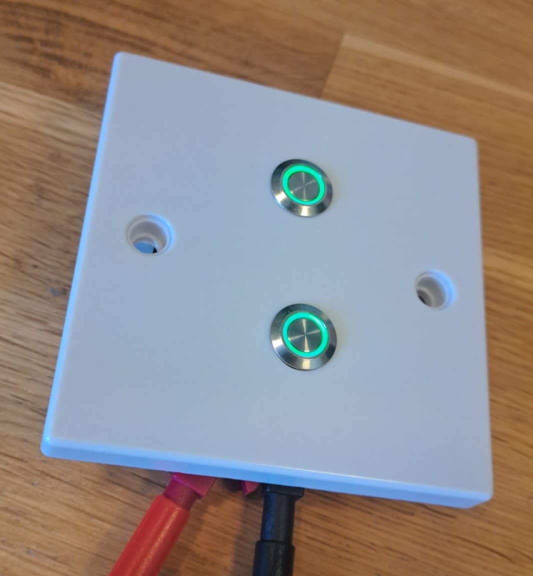
Version 0 - Febuary 2021
The very first prototype I made was the simplest — two off-the-shelf buttons mounted in an electrical blanking plate. This connected to a controller in a central location that handled all processing, reducing cost and complexity.
What I like about this design
- Simple design and manufacturing process
- Extremely cheap to produce
- Backlit buttons useful for locating switches in the dark
What I should look to change:
- Buttons are difficult to press for people with reduced motor control
- Too simple — I wanted to challenge myself with more complexity
- Not elegant enough for a modern household
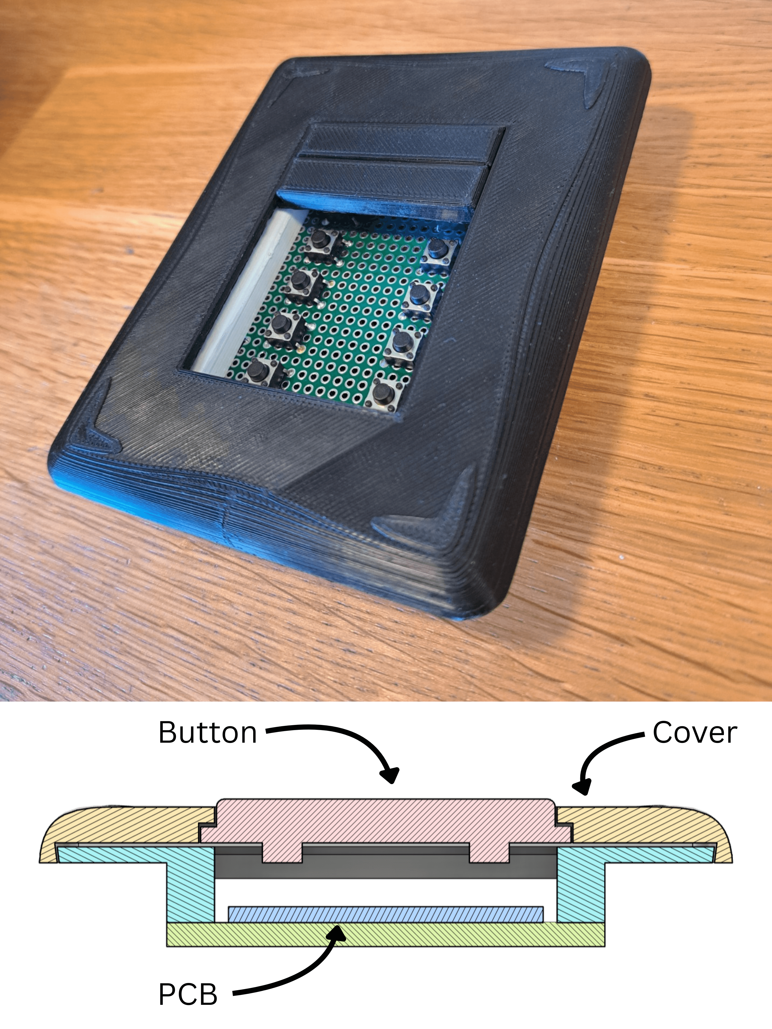
Version 0.5 - November 2021
After the first prototype I realised I would never achieve the user experience I wanted with off-the-shelf components. I decided to move towards an entirely custom 3D-printed design.
In this design the buttons are held loosely in place by the cover, and when pressed they press against the psuh buttons, triggering them.
What I like about this design:
- 3D printing allows unrestricted design control and in-house prototyping
- Simple to assemble
- Shape and size of the buttons allow text to be engraved (eventually)
What I should look to change:
- Buttons rub and catch on each other, creating an unreliable user experience
- Buttons feel loose to the touch
- No backlight on the buttons — I planned to address this in a much later version after finalising the button mechanics
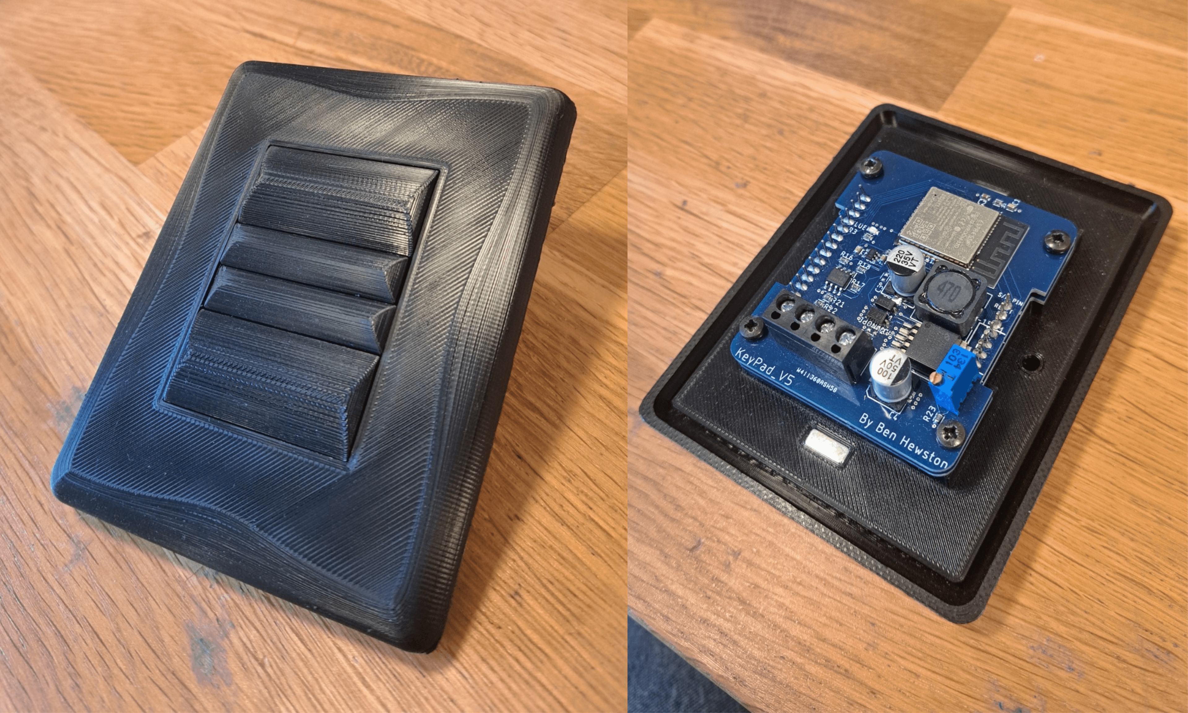
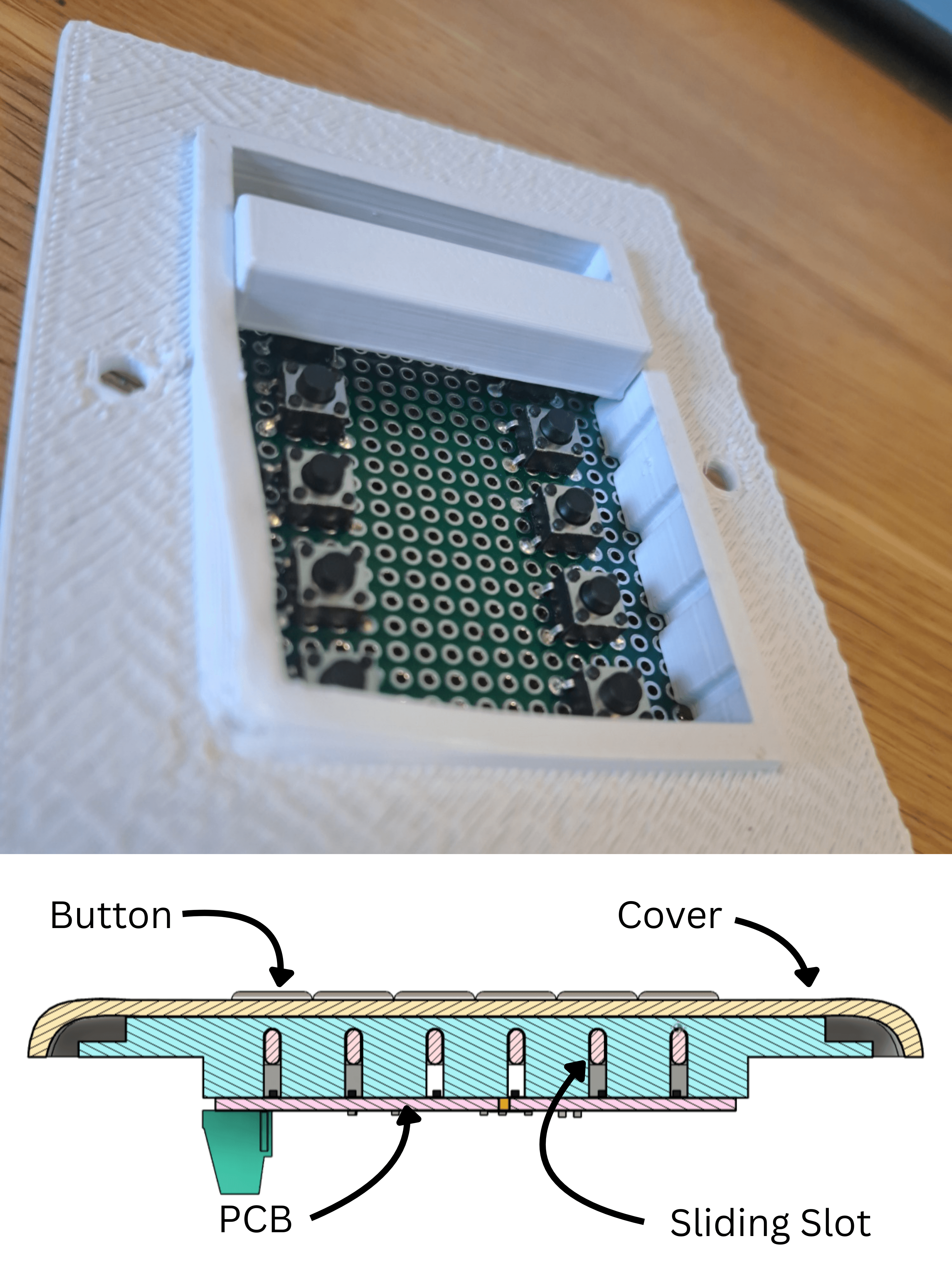
Version 1 — March 2022
Mechanical
In this design I moved to a 3D-printed slot mechanism. Each button has two nibs that slide inside the main body's slot channels, allowing only vertical movement.
What I like about this design:
- Slots only allow vertical movement — limiting rubbing against other buttons
- You can remove the cover without removing the buttons
- Buttons don't wiggle when touched
What I should look to change:
- Friction in the slots makes the buttons difficult to press
- Slots are difficult to manufacture consistently
- If the button is pressed on one side it can jam
- The cover is currently held with just friction, this is unreliable when it's installed on uneven walls
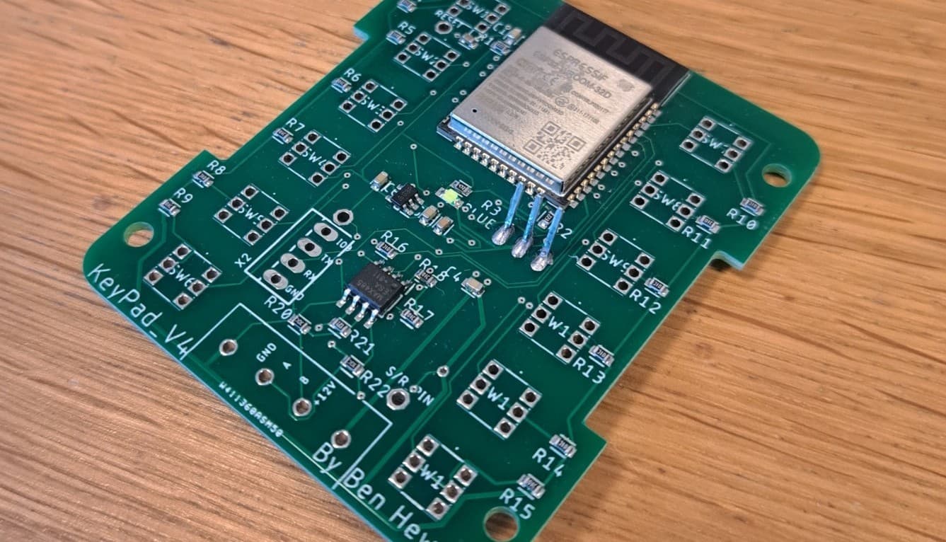
Electronics
I decided creating my own PCB would be the most effective approach.
After testing multiple designs on breadboards, I ended up using an Arduino Nano, MAX485, and L7805.
This allowed me to power the board with 12V while monitoring and sending button presses to the controller via RS-485. I also added WS2812B addressable LEDs for backlit buttons and switched to push buttons with a more uniform pressing force.
After ordering the PCBs from a manufacturer, I hand-assembled them using a hot plate and soldering iron.

What I like about this design:
- The new push buttons provide longer travel and a more uniform activation force
- RS-485 allows long-distance communication
- WS2812B LEDs allow colour-changing backlights
- The screw terminal connector makes installation easier compared to direct soldering
What I should look to change:
- PCB is too big to fit in standard electrical backboxes
- SMD buttons melt during installation — I need to switch to through-hole switches
- Using an Arduino Nano is expensive compared to alternative microcontrollers
Version 2 - July 2022
Mechanical
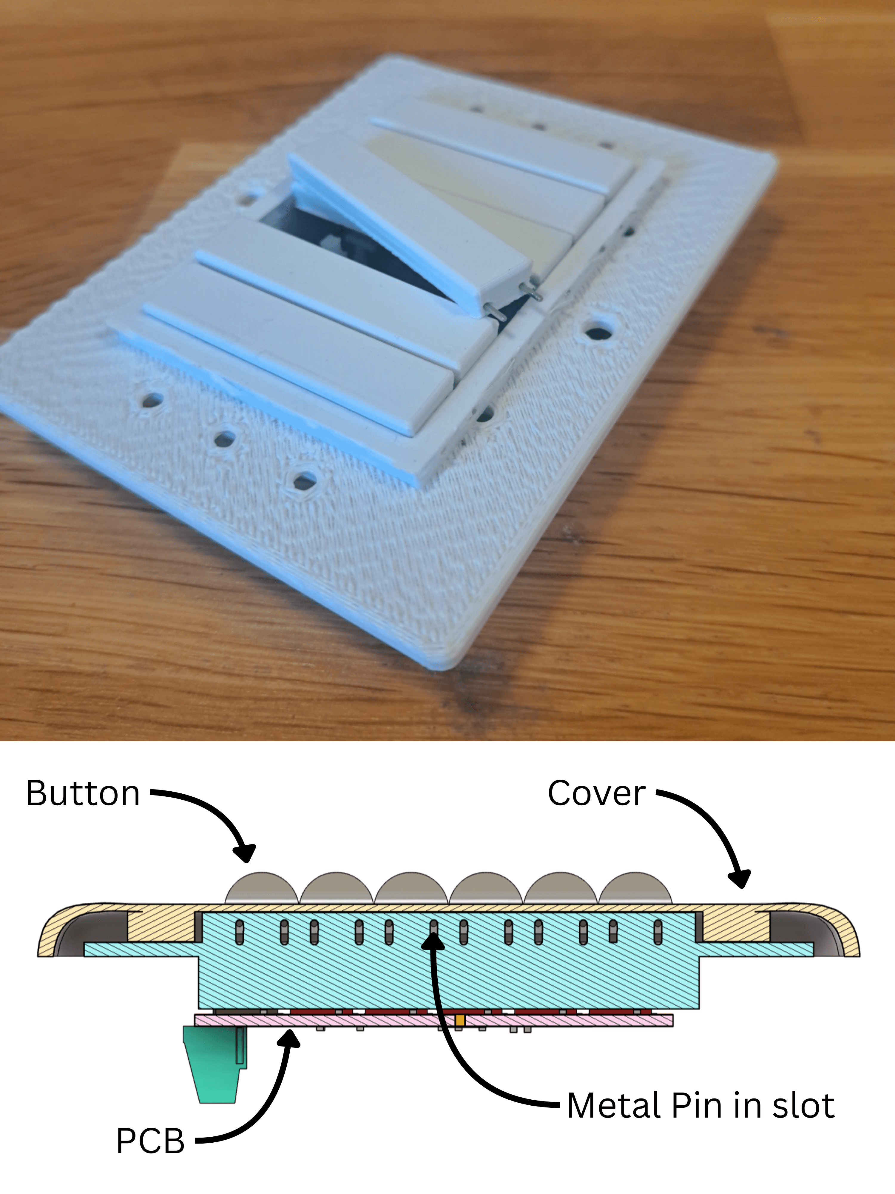
In this design I experimented with different materials to reduce friction in the buttons. I created this version using small metal pins, press-fitting them to create a low-friction slider mechanism.
What I like about this design:
- The metal pins allowed low-friction movement
- Changing the button profile to an inverted trapezoid helped prevent rubbing between buttons
- The strength of the pins let me reduce the button height, making the design thinner overall
What I should look to change:
- Buttons tilt uncontrollably when pressed, creating an uncomfortable user experience
- Buttons can still jam if pressed on one side
- Slot tolerances allow lateral movement, creating uneven gaps between buttons
Electronics
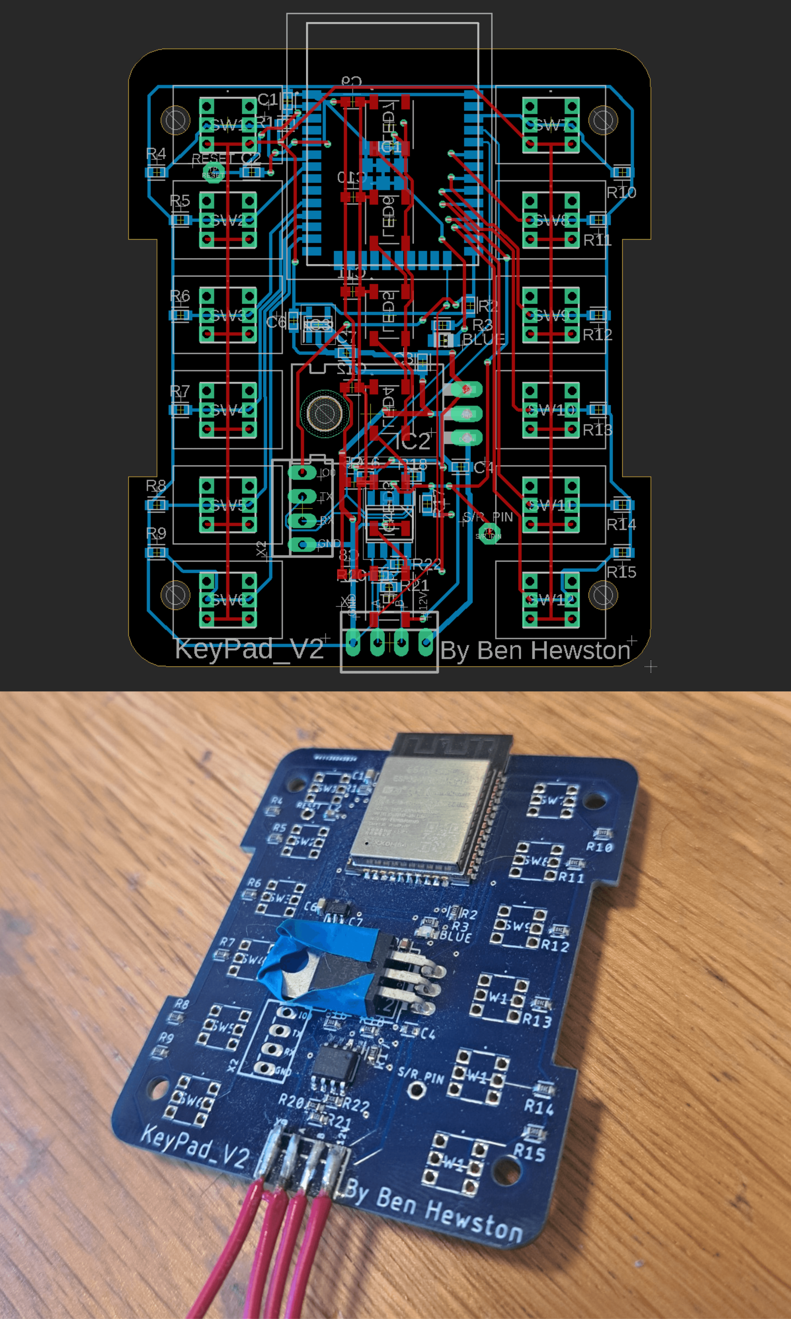
In this design I switched to an ESP32-based board.
To fit the ESP32-WROOM microcontroller and its power circuitry, I had to move the push buttons closer to the edges.
What I like about this design:
- New push button placement reduces the chance of jamming
- ESP32 is much cheaper than the Arduino Nano
- Built-in Wi-Fi enables future over-the-air (OTA) programming
- Mostly SMD components, reducing hand soldering work
What I should look to change:
- The L7805 regulator gets very hot during use — a heatsink is needed
- The L7805 is too close to other components and risks shorting
- The ESP32’s onboard antenna sticks out over the edge of the board
Version 3 - October 2022
Mechanical
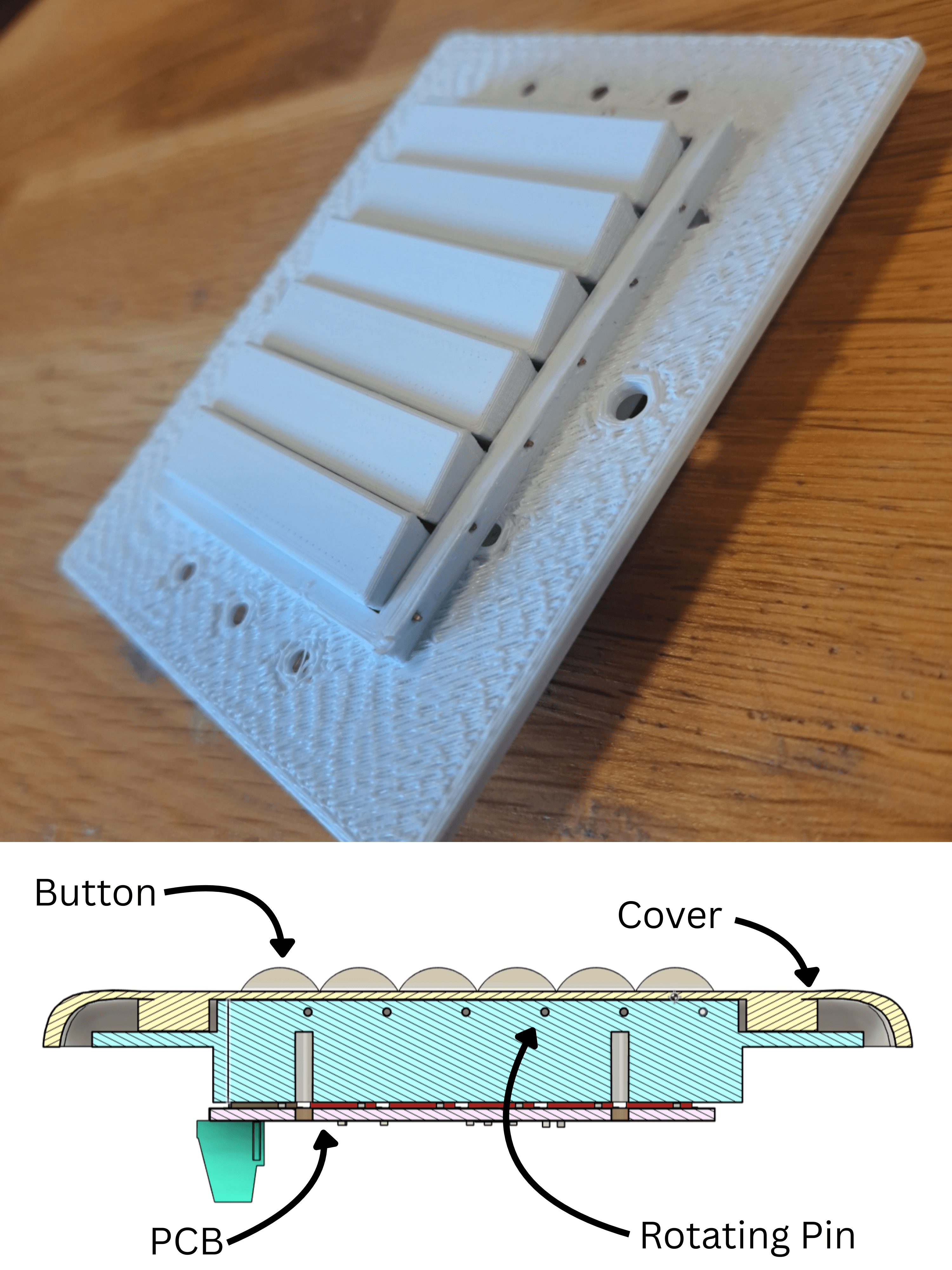
In this version experimented with another button mechanism.
I used the metal pins again to act as the hindge pin, which the buttons rotate around when pressed.
What I like about this design:
- Buttons can’t be pressed unevenly — no jamming
- Rotation-only movement keeps even gaps between buttons
- Button action feels more controlled and solid
What I should look to change:
- Buttons over-rotate and stick out past the switch surface
Electronics
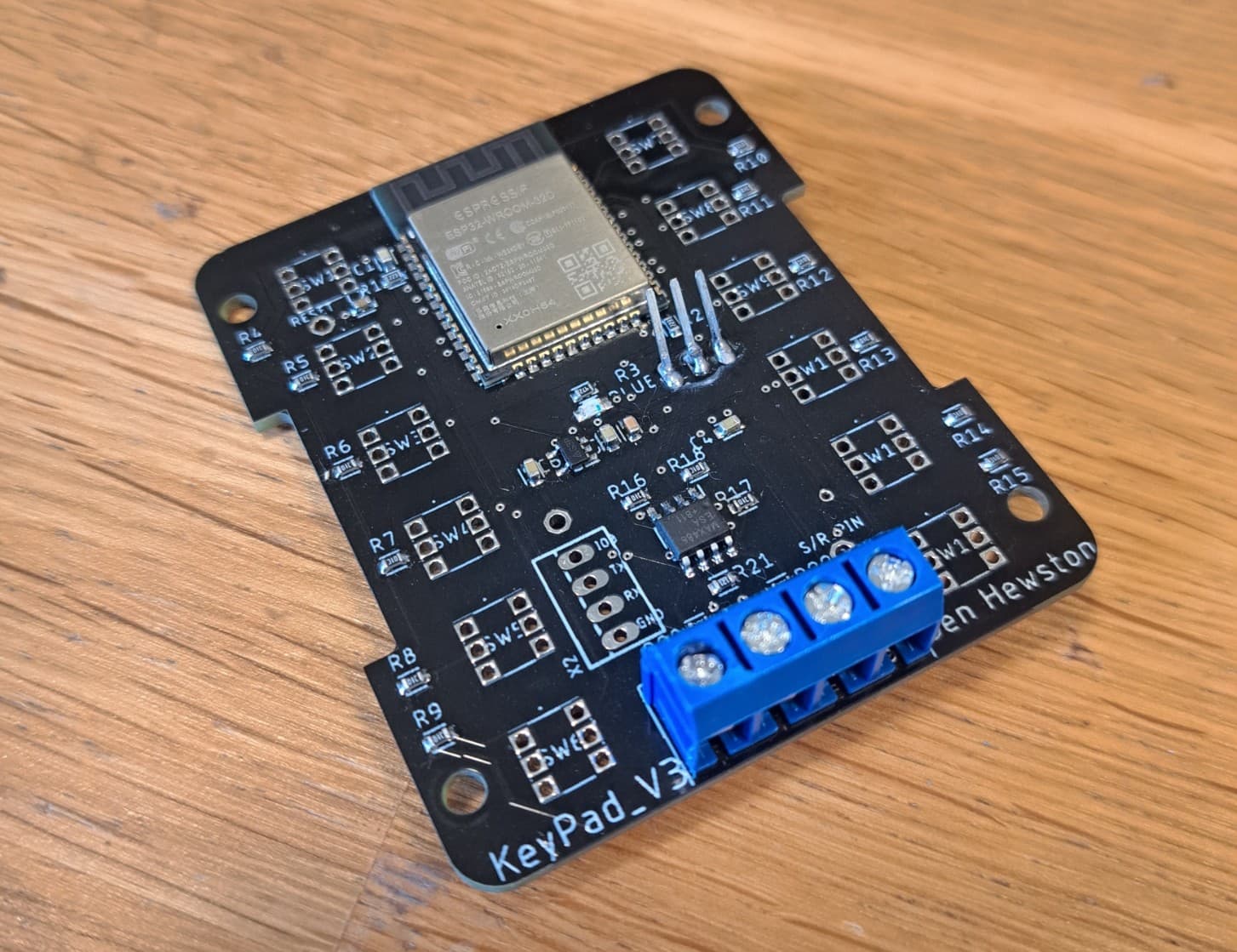
This version included mostly small fixes: - L7805 now has an embedded heatsink in the PCB for heat dissipation - Terminal block footprint corrected - ESP32 no longer extends off the edge of the board - Added a 3.3 V pin for powering the ESP32 during programming
Version 4 - October 2022
Mechanical
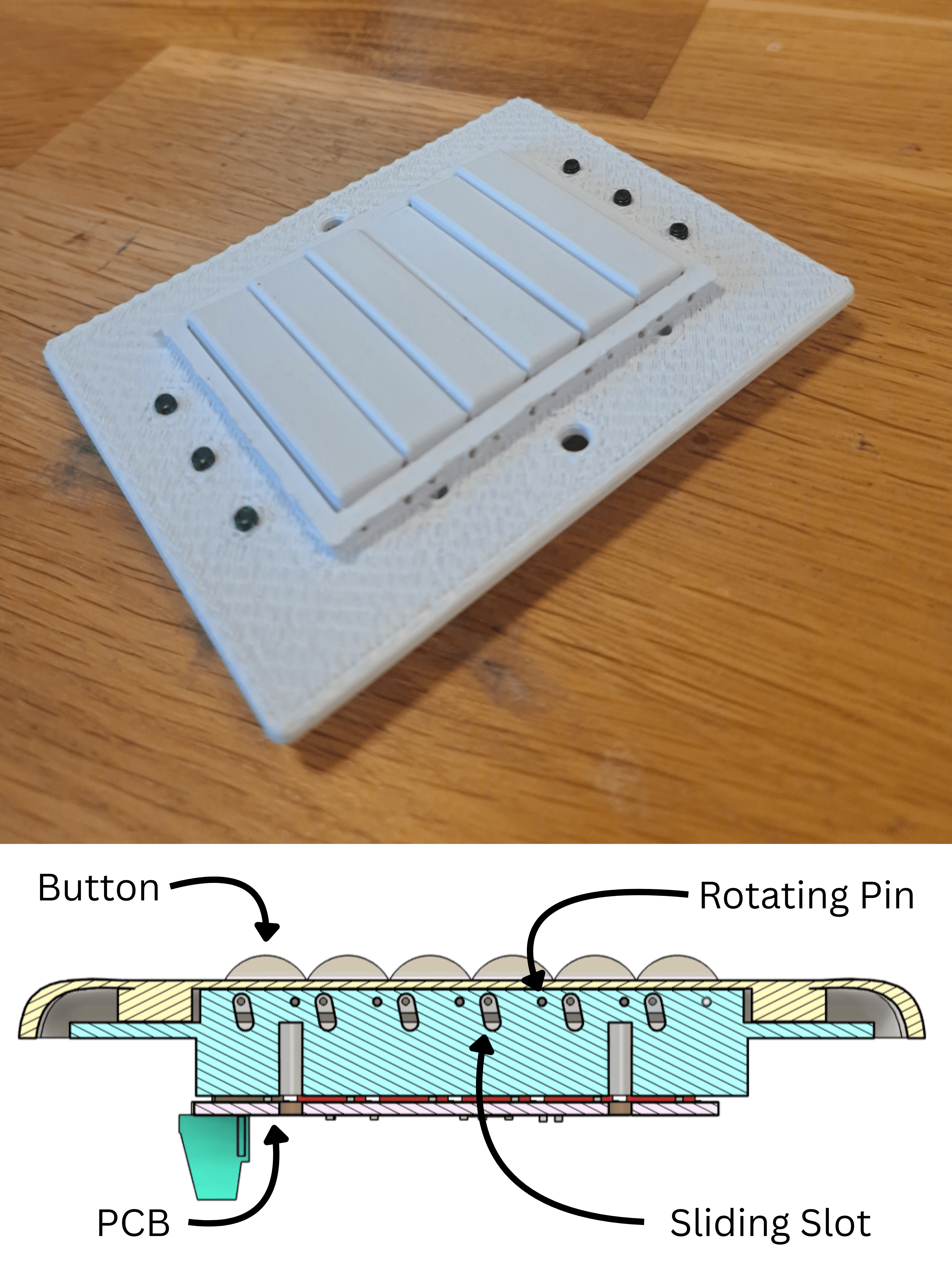
In this design I combined ideas from Versions 2 and 3: using a rotating pin hinge along with a slot to allow button presses but prevent over-extension.
I also experimented with using screws to hold the cover in place. Instead of being screwed on normally, the cover was pressed onto the screws and was held by friction.
This design was installed in over 30 locations around my house, until it was replaced by version 5
What I like about this design:
- Very little friction when pressing the button
- Buttons have a solid, satisfying push
What I should look to change:
- The friction-fit screw method was unreliable — covers occasionally fell off
Electronics
The only change in this version was fixing a wiring mistake: I had previously swapped the TX and RX lines between the ESP32 and MAX485, which prevented communication. Once corrected, the board could finally talk to the main controller.
Version 5 - July 2024
Mechanical
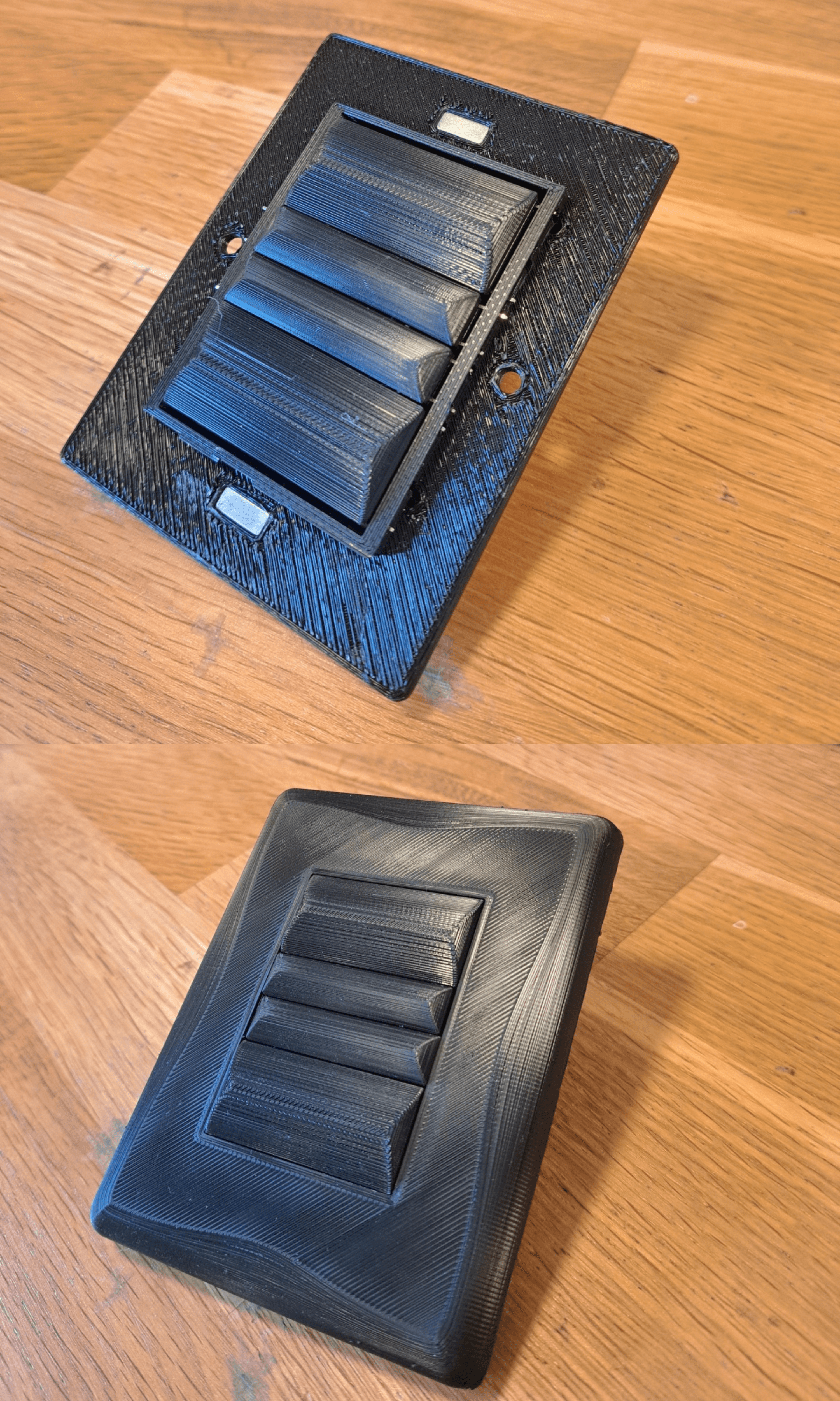
Based of the real world data from Version 4, I created an updated version which is now installed around my house.
This version reused the button mechanism from Version 4. I experimented with larger button sizes and magnets to hold the cover in place.
What I like about this design:
- Larger buttons are much more comfortable to press
- Magnetic covers make installation and removal easy, even on uneven walls
- Adding a curved bump to the buttons improved aesthetics and made pressing more pleasant
What I should look to change:
- Because the hinge is on one side, some areas of the button can’t be pressed
- Metal pins can bend if pressed too hard
- The surface finish doesn’t look professional
Electronics

In this version I replaced the L7805 with an LM2596-based power supply. This provided a more stable voltage and reduced heat output.
Because of the additional components, I required more PCB space, so I designed a stacked PCB connected with 2.54 mm headers.
What I like about this design:
- The switch now produces very little heat
- Reoriented terminal blocks route wires over the back of the switch rather than straight out, greatly improving installation
What I should look to change:
- Cheap push buttons wear out under heavy use
- High actuation force makes pressing less comfortable
- Unlike standard switches, there is no satisfying “click,” reducing user experience
What I Learned
Building this smart switch taught me far more than I expected when I started. Some of the most important lessons included:
- Iterative design is essential — every version solved something and broke something else, and that cycle is what actually pushed the design forward.
- Mechanical tolerances matter — 0.2 mm in a 3D print doesn’t sound like much, but it’s the difference between a smooth button and one that jams.
- Electronics heat management is critical — switching from linear regulators (L7805) to switching regulators (LM2596) made the design practical for real-world use.
- User experience is as important as functionality — the feel of the buttons, the clickiness, and aesthetics mattered just as much as the electronics inside.
Future Improvements
Everyday the light switches are used I collect more data on how to improve them and there’s still plenty of room for improvement:
- Better buttons — replace the cheap tactile switches with higher-quality alternatives that provide a crisp, satisfying click.
- Add a click — I want to add a secondary mechanism to cause the button to make a click sound when pressed.
- Stronger mechanics — relying on the metal pins works, but they bend if you push too hard. I’d like a more solid hinge system.
- Cleaner look — right now they still look “3D printed.” At some point I’d love to try resin casting or even injection molding to make them feel like real products.
- New power source — I want to look at powering the board with AC, increasing the amount of power I can transmit over cat5e
- Firmware updates — I want to add OTA updates, and allow configuration via a SoftAP.
- Certification — if I ever wanted to sell these, I’d need CE/UL safety approval and compliance with proper electrical standards.
- Author

- Name
- Ben Hewston